Changes have been made to the PXU that warrants new captures, plus I acquired a new oscilloscope as well. Because of this, this isnt accurate with the current version of PXU. I hope when things arnt as busy as they are now, I’ll do new captures. I am going to leave it up as some might find it interesting. : )
Some expressed some interest in technical and capability of PXU. We’ll touch on that but first I need to make a few bullet points.
- I’m not an EE (Electrical Engineer).
- My goal is simple. Not be worse than the OEM power supplies… Figured not being worse than an 20+ year old power supply would be a good starting point. Don’t expect Seasonic levels of quality.
- Be a drop in solution, while being able to adapt to various other input solutions.
Some Functions of the power supply.
- Over Volt Protection.
- Over Current Protection.
- Over Heat Protection.
- Main 5V rail @14 Amps, 12v Rail @ 3.5Amp, and the 3.3/5v rail at 5.5Amp
- Mimicking the OEM supplies.
- Modular input options.
- Single PCB for all revisions.
In terms of heat. The warmest parts of the power supply are the buck for the hefty 14amp 5volt rail and the 3.3v LDO regulator used for internal logic control and the standby rail for 1.0-1.4s. Using a P2 Pro thermal camera on my phone to measure. Temperature was in the low 60s centigrade on the 5v buck converter, varying a few degrees due to room temperature. This was powering a 1.1 revision console with a CPU upgrade, 128MB RAM, dual 2TB 7200RPM WD Enterprise Hard Drives, and a Bitfunx HDMI adapter for 8 hours.
Now, how much ripple does the voltage rails have? Hear this one a lot, we’ll get there. First I wanted a baseline, for that I used the main screen of PrometheOS with it’s default theme. This provided an easy constant and repeatable load. Using the same 1.1 rev console as before, I did drop to a single HDD. Simply so I did not have to wrestle two drives and possibly damage one or accidentally hit live AC. In hindsight I should of just cut a whole in the bottom of a junk case to get to where I wanted. Might do that in the future… The scope I’m using is a Rigol DS1202Z-E with 2ch at 200Mhz. When measuring with the probe, I used the spring clip to keep the inductive loop as small as possible. No persistence, AC coupling, span of 1ms and 5ms, and no persistence. I tested directly on the power supplies. For the PXU that is where the wire harness solders in, the OEM power supply was on the bottom where it’s wires are soldered at.
Minebea
First lets take a look at the hefty 5v rail…

65mV peak to peak AC ripple.
12v I had to switch to 50mV divisions.

218mV Peak to peak.
3.3v is back to 20mV divisions.

Interesting… Let’s zoom out to 5ms.

Okay… It’s consistent at least. 84mV peak to peak.
How does PXU compare?
Same hardware config as before:
Starting off with the 5V rail…

Not bad in comparison… Only 29mV ripple vs 65mV with the Minebea.
Looking at the 12v rail now.

Looks a little wild at first, however we didn’t have to switch to 50mV divisions, 78mV peak to peak vs the 218mV.
Now, the 3.3v rail.

Okay… Interesting… I did a 5ms with the Minebea, let’s do that again.

Only 58mV ripple vs 84mV on the Minebea.
Why does the 3.3v rail look like this? The buck converter has a tolerance of 1%. The difference between the two segments you see is approx ~25mV, 1% of 3.3v is 33mV. Our deviation is within the 1% tolerance. While a more linear line is desired, I’m not sure it really going to matter. Considering I have to switch to 100mV divisions for some of the other OEM supplies.
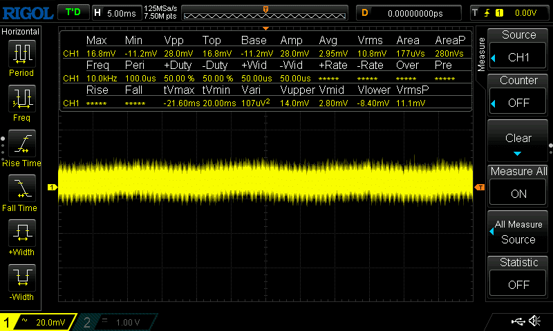
Now, Let’s load a game. Again I needed something predictable to make it a fair comparison. Decided to load Halo 2 since it’s an iconic title and just sat at the screen where you test your controls.
I’m also going to deviate a little. To try to make a fair comparison across the 4 power supplies I’m going to test. I’m switching to a stock 1.0 to test the Minebea, and a stock 1.3 for the Foxlink and Delta. I would ideally would like to stick with the rev board for consistency, however I don’t have a Delta for the 1.0 currently. Since we are changing board revisions, take everything with a grain of salt… Both the 1.0 and 1.3 have been recapped with new Panasonic FR series caps from Digikey. Also going to use 5ms divisions so help see a larger snapshot.
Minebea In Halo 2:
5V

12V at 50mv divisions

Finally the 3.3v, back to 20mV divisions.

Foxlink, 1.3 Rev Console, Running Halo 2.
Note: I had to change our divisions to 100mV.
Starting with 5V

12v

3.3v

Delta, 1.3 Rev Console, Running Halo 2.
Note: we’re at 100mv divisions still.
5v.

12V

3.3v

Now, How does the PXU compare? I’m going to do both the 1.0 and the 1.3 with the PXU. Maybe where the Delta and Foxlink are for the 1.3 instead of the 1.0, maybe that has something to do with higer peak to peak on the 1.3?
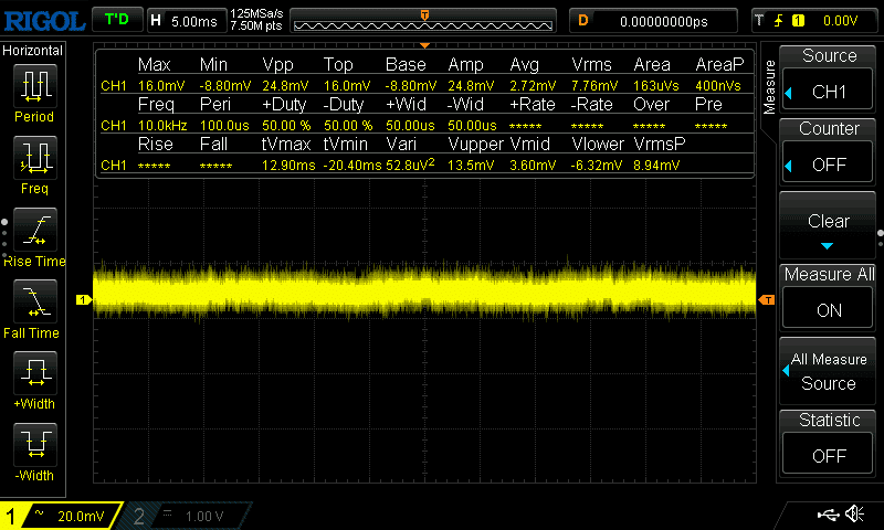
PXU, 1.0 Rev Console, Running Halo 2
5V

12V

And the 3.3V

5V and 12V has some improvement. The 3.3V I would call a tie. Man that is a wild looking signal. I can see why they did a 5v rail for the 1.6s, surprised it took them as long as they did.
PXU, 1.3 Rev Console, Running Halo 2
5V

12V

3.3V

Now… onto 1.6s!
We’re going to start off with the PXU. (Tired of shocking myself with 110v at the moment).
PXU, 1.6 Rev Console, Running Halo 2
5V
12V

What would be the 3.3V on the 1.0-1.4s is a 5V on the 1.6s
Yeah… They made massive improvements with this rail vs the older 3.3v rail!
Annnnd… I dont have a working OEM power supply for the 1.6…. Kinda the whole reason I started down this endeavor. ¯\_(ツ)_/¯